Casey GrothausCasey Grothaus
ProjectsCompleted

Remote door lock

A toy RC remote, a gear motor, and a custom board that locks a door.

The first hardware project I actually finished. It started as a four-second motor test on a breadboard and ended as a door lock running on a circuit board I designed and had made.

Status
Completed
Built
August 2026
Built with
Arduino NanoTB6612FNGKiCadPythonJLCPCB
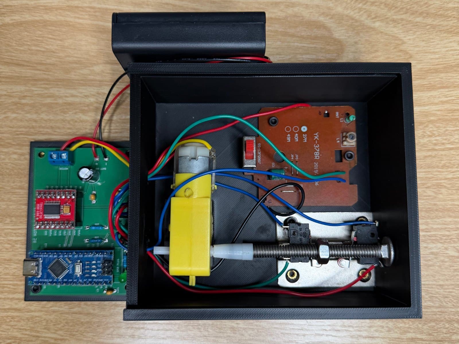
Remote door lock: the finished build in its enclosure, with the Carrier PCB v1.1 carrier board beside itThe build
Remote door lockAugust 2026

The story

I wanted to finish one hardware project, start to end.

Back in 2019 I bought an Arduino starter kit and got stuck every time the project needed real code. This was the first build where that wasn't the wall. AI wrote the firmware and the board files with me checking each step, and I got to spend my time on the wiring, the soldering, and the mechanism.

The goal was small on purpose: push a stick on a toy RC remote and a motor turns a lock one way, push it the other way and it turns back. Simple enough that I could get it working on a breadboard, then take it all the way to a real printed circuit board.

It's done. The board is soldered, the switches tell the motor where to stop, and the whole thing runs off four AA batteries.

How it works

The remote is a cheap toy transmitter and receiver. The receiver has two output lines: one goes high when the stick is pushed forward, the other when it's pulled back. Those two lines are the only input the board gets.

The Nano watches those lines and drives a TB6612 motor driver. Forward runs the motor toward the locked position, reverse toward unlocked, and it ignores new presses while a run is in progress. Two microswitches at the ends of travel stop the motor when it gets there. If a switch never trips, an eight-second timeout stops it anyway and prints a warning over serial.

A few things are there to keep it from misbehaving. The switches are wired normally closed, so a broken wire reads as "at the limit" and stops the motor instead of grinding. Both remote lines high at once is treated as a fault and stops everything. And at boot the firmware reads its own motor pins back to make sure nothing is shorted before it lets the motor move.

  1. InputToy RC remote

    Push the stick forward to lock, back to unlock.

  2. ReceiverRC receiver

    Its two output lines, F and B, go to pins D2 and D3 on the board.

  3. BoardArduino Nano

    A small state machine: idle, running forward, running reverse. It only reacts to a fresh press.

  4. DriverTB6612FNG motor driver

    Takes the direction and speed from the Nano and switches the battery power to the motor.

  5. OutputTT gear motor

    The yellow hobby motor turns the lock.

  6. FeedbackTwo end stop switches

    One at the locked position, one at unlocked. When the lever trips, the motor stops.

Inside the build

What I used.

  • RC motor carrier PCB v1.1The custom board that replaced the breadboard. Sockets for the Nano and the driver module, the regulator, pull-downs, headers, and screw terminals. Designed by me, made by JLCPCB.
  • Arduino NanoRuns the firmware. Sits in a socket on the carrier board.
  • TB6612FNG motor driver breakoutDrives the motor. Replaced the L293D from the breadboard version and drops far less voltage.
  • TT gear motorThe yellow hobby motor that turns the lock.
  • Toy RC transmitter and receiverThe remote. The receiver's forward and back lines are the board's only input.
  • KW12-3 roller lever microswitchesx2End stops at the locked and unlocked positions, wired normally closed so a broken wire fails safe.
  • 4x AA battery holder with switchPowers the whole thing. The holder's switch is the power switch.
  • MCP1702 5V regulatorMakes the 5V logic supply from the battery pack.
  • Resistors, capacitors, and a power LEDTwo 10k pull-downs on the receiver lines, a 470uF cap on the motor supply, decoupling caps, and an LED so you can see the regulator is alive before anything else is plugged in.
  • Female pin sockets and screw terminalsEvery module is socketed so a mistake is recoverable. Battery and motor go in screw terminals.

Timeline

  1. Day 1Summer 2026

    Getting back into hardware

    The first video was just about getting my hands on a breadboard again. One button and a stepper motor: press it and the motor turns for four seconds, then stops. Press it again and it turns the other way for four seconds. Nothing more than that, on purpose.

  2. Day 2

    A motor that runs on a remote

    Same idea, but the button became a toy RC remote. An Uno, an L293D driver chip, and the receiver on a breadboard: push the stick and the motor runs for four seconds, then stops. The project folder is still named after that test.

    With the remote switched off, the motor would start on its own. The receiver's output lines float when it has no power, and the board read the noise as presses. Two 10k pull-down resistors fixed it. The motor was also slow: the L293D eats about two volts, so the motor only saw around three.

  3. Day 3

    Making it a door lock

    Hooked the motor up to an actual lock. Forward on the controller turns it to the locked position, back turns it to unlocked. I added a microswitch at each end of travel so the motor stops when it gets there instead of running on a timer, kept the timer as a safety cutoff, and had the firmware refuse to run into a switch that's already pressed. Same day, I designed and 3D printed an enclosure so all of the components had somewhere to live instead of a breadboard on the desk.

  4. Day 4August 2026

    The finished lock

    Everything hooked up and working. The carrier board in its enclosure, the motor on the lock, the end stops in place, and the whole thing running off four AA batteries. Push the stick forward and the door locks. Pull it back and it unlocks.

Open to partnerships

Curious what came next?

This was the first hardware project I finished. The AI Desk Robot is the one I'm building now, and it's a lot bigger.